Interfacing VGA in VHDL (FPGA)
A little background
The Design Process
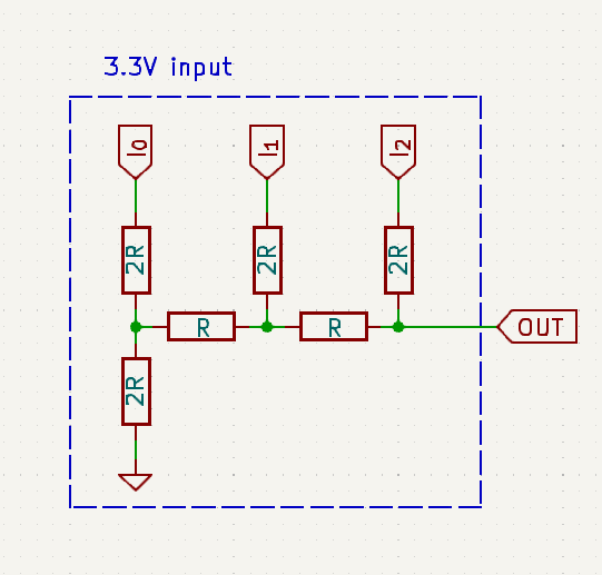
VGA needs an analog signal, while one can use a DAC chip for each color, it would be much simpler (and cheaper) to just use an R2R ladder.
R2R
Not much to say about it, a simple R2R would nicely convert Digital
values to Analog, I have decied to use 3 bits for each color, for a total of \(2^3 =
8\) levels of a color. Since VGA uses 3 different colors, I get a
total of \(8\times 3 = 24\) colors, which isn’t that bad.
Voltage Level
VGA uses \(0.7V\), while my FPGA has a logic output of 3.3V, this could easily be solved using a voltage divider.
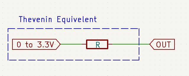
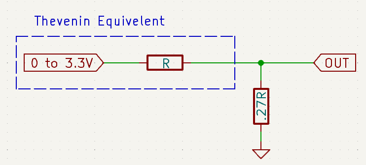
Luckliy, The thevenin equivalent circuit of R2R ladder can easily be found, then one can construct a voltage divider to achieve a value of \(0.7V\) (or lower).
\[3.3V \times \frac{x}{x + R} \le 0.7\]
Solving for \(x\), we see that \(x \le 0.27R\).
Choosing Values for R
Now I know the I need the following values, \(R\), \(2R\) and less than \(0.27R\). I will spare you my trail-and-error, I found that \(5K\Omega\) seems like a good choice. The nearest values I had with me are \(5.1K\Omega\), \(10K\Omega\) and \(1K\Omega\).